
Advanced Static Var Generator ASVG
Advanced Static Var Generator (ASVG)
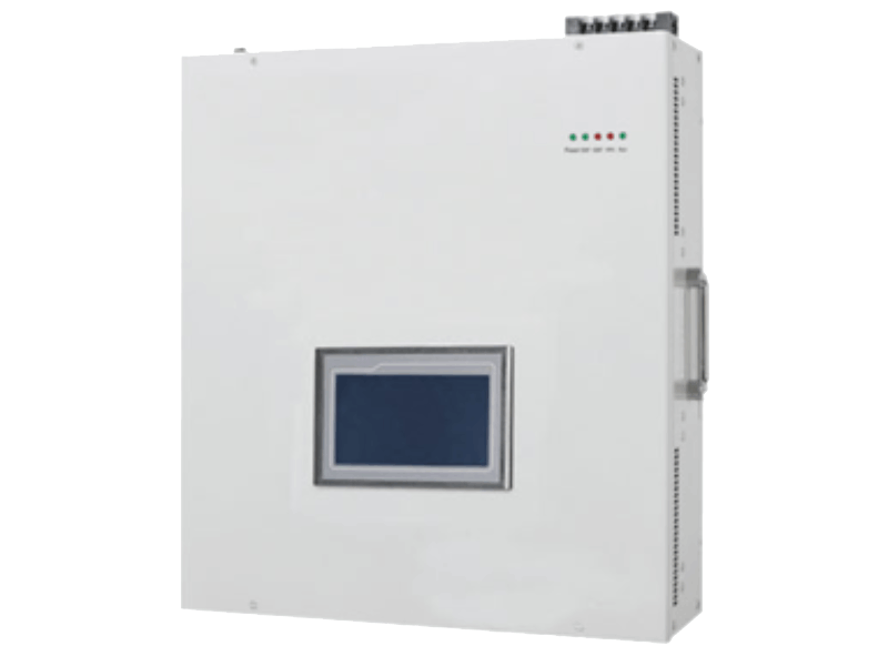
ASVG- is a new type of dynamic reactive power compensation product, combining power factor correction and harmonic mitigation in one unit. It provides the same dynamic performance for compensating reactive power as the SVG with the added benefit of combining harmonic mitigation and controlling three phase unbalance. Advanced static var generators (ASVGs) are high-performance, compact, flexible, modular, and cost effective to provide immediate and efficient responses to power quality problems in high and low voltage power systems.
Product Features
- Reactive power compensation: Cos Ø = 1.00
- Capacitive and Inductive compensation: -1 to +1
- All the features and benefits of the SVG. – Mitigation of 3rd, 5th, 7th, 9th, 11th harmonic orders
- Unit capacity can be selected in any proportion between power factor correction and harmonics correction
- Capacitive inductive load-1~1
- Current unbalance correction can correct for load unbalance across all three phases
Working Principle
With external CT detecting the load current in real time, internal DSP calculate and abstract the reactive power and harmonic content of load current, then send the PWM signal to internal IGBT and adjust the phase and amplitude of the output voltage on the AC side of the inverter or directly control the phase and amplitude of the current on the AC side of the inverter, so as to quickly absorb or emit the required reactive power and harmonic current, and realize the purpose of fast dynamic adjustment of reactive power and harmonic compensation. Not only the reactive current of the load, but also the harmonic current can be tracked and compensated.
Ideal For
- Plants with high facing transformer overheating
- Industries with fluctuating loads
- Plants with high harmonic distortion
- CNC machines & automation lines
- VFD and inverter-based systems
- Solar power plants
- Data centers
- Textile, steel, paper, and plastic industries
- Hospitals and commercial buildings
- Facilities facing power factor penalties
Key Benefits
- Real-time power factor correction (up to 0.99)
- Harmonic mitigation up to 25th order
- Reduces electricity bill penalties
- Improves transformer and cable life
- Eliminates capacitor bank-related issues
- Fast response time (<10 ms)
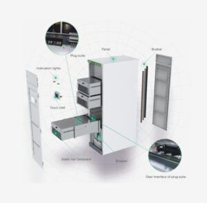
- Compact and modular design
- Low maintenance solution
- Enhances overall power quality
Technical Advantages
- IGBT-based advanced PWM technology
- Dynamic reactive power compensation
- Three-phase unbalanced load correction
- Simultaneous harmonic filtering & PF improvement
- Intelligent DSP-based control system
- Automatic load tracking
- No overcompensation risk
- Works efficiently even at low load conditions
- Easy integration with existing electrical panels
Electrical Specification | |
Rated Voltage | 400V(300~456V) |
Rating | 30/50/75/100kVAr |
Circuit Topology | Three Level IGBT |
Network Configuration | 3P3W/ 3P4W |
Mains Frequency | 50/60Hz±5% |
Reactive Power Compensation Capability | Both inductive and capacitive reactive power |
Multi Compensation Mode | Harmonic compensation(Up to 25th order), reactive compensation, three-phase load unbalance compensation |
Target Power Factor | Adjustable from -1.0 to +1.0 |
Overall Response time | ≤5ms |
Multi devices in parallel | Up to 12 sets can be connected in parallel |
Output current limit | Automatically limited within 100% of rated capacity to output |
Control Technology | |
Switching/control frequency | 25.6kHz |
Controller | DSP+FPGA |
Control algorithm | Intelligent FFT, Self-adaptive control algorithm |
Communication protocols | communication interface adopts RS485 and CAN bus, supporting mobile phone APP operation |
Physical Specification | |
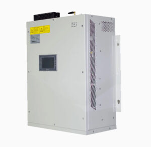
Human Machine Interface | 7 inch touched LCD HMI |
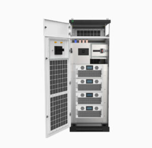
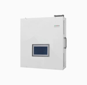
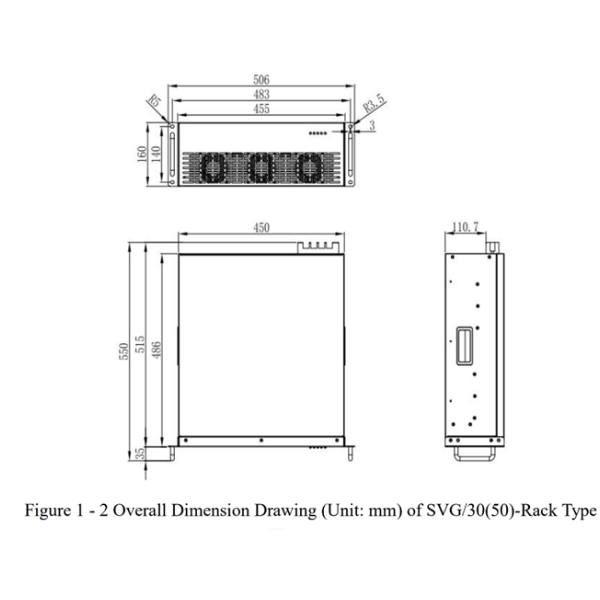
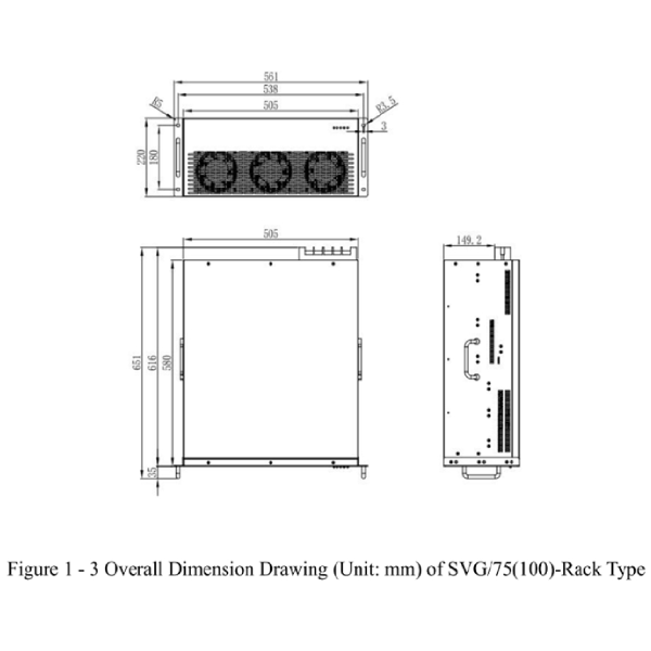
Installation method | Rack mounted, wall mounted |
Cooling method | Speed regulation intelligent air cooling PWM Fans |
Level of protection | IP20~IP54 |
Environmental Specification | |
Ambient temperature | -20 ~ 55 ℃ (rated power output) |
Environment temperature | -30~70℃ |
Relative humidity | 95 % at a maximum, no condensation |
Altitude | Below 1500 meters above sea level |
Cooling requirements | Require well ventilation, and the air vent can be opened through the cabinet door, or a fan installed in the cabinet |
Typical Applications

Industries using VFD-driven motors

Solar inverter-based plants

Plastic, textile, metal & food processing plants

Data centres & IT parks

Commercial buildings with heavy non-linear loads

Hospitals (MRI, CT, X-ray, critical loads)
Product Portfolio
Mechanical Drawings
Why is the CT (Current Transformer) location critical for ASVG operation?
The Current Transformer (CT) is the primary feedback device used by the ASVG controller to calculate the reactive current demand of the electrical system. An incorrectly installed CT can lead to inaccurate compensation, unstable operation, or even reactive power injection in the wrong direction.
For optimal performance, the CT should be installed at the Point of Common Coupling (PCC), ensuring that all downstream loads are included within the measurement zone while the ASVG itself remains outside the CT measurement loop. Proper CT polarity (P1/P2 and S1/S2) and phase sequence must also be verified during commissioning.
What happens if the CT polarity is reversed during commissioning?
Reversed CT polarity causes the controller to interpret reactive power flow incorrectly. Instead of compensating inductive reactive power, the ASVG may inject additional reactive current into the system, causing:
- Power factor deterioration
- Overcompensation
- Continuous hunting
- Leading PF alarms
- Increased converter current
- Protection trips in severe cases
Can multiple ASVG units operate in parallel without communication?
Yes.
Modern ASVGs use intelligent load-sharing algorithms that automatically distribute reactive power demand among multiple units operating on the same bus.
Each controller continuously measures the system requirement and contributes proportionally according to its rated capacity, ensuring balanced current sharing without circulating reactive currents between units.
For larger installations, communication-based master-slave control may also be implemented for enhanced coordination.
How does ASVG prevent overcompensation under light-load conditions?
Unlike capacitor banks, ASVG does not inject fixed reactive power.
Its controller continuously calculates the instantaneous VAR demand and automatically reduces compensation current as system loading decreases.
When reactive demand becomes zero, the ASVG output smoothly reduces to zero without switching operations, eliminating the risk of leading power factor.
Can an ASVG compensate reactive power generated by VFDs operating at different load levels?
Yes.
The reactive power requirement of Variable Frequency Drives continuously changes with motor loading.
ASVG continuously tracks these variations and dynamically injects or absorbs reactive current, ensuring stable power factor even when multiple VFDs accelerate, decelerate, or operate under varying torque conditions.
Does ASVG require derating under high ambient temperatures?
Like all power electronic equipment, ASVG performance depends on thermal management.
If ambient temperature exceeds the specified operating limit, the controller may automatically reduce output current to protect IGBT modules and DC bus components.
Proper ventilation, air circulation and clearance around the unit are essential to maintain continuous rated performance.
Why is transformer capacity important while selecting an ASVG?
Reactive power demand is closely related to transformer loading.
Selecting an ASVG based only on transformer rating may result in under-sizing or over-sizing.
A proper selection should consider:
- Maximum kW demand
- Existing power factor
- Target power factor
- Load diversity
- Harmonic profile
- Future expansion
A detailed load analysis provides the most accurate ASVG rating.
Can ASVG improve the available capacity of an existing transformer?
Yes.
When a transformer supplies excessive reactive current, part of its current-carrying capacity is occupied by non-productive reactive power.
By locally supplying reactive power, ASVG reduces transformer current, allowing a greater portion of the transformer capacity to deliver useful active power without replacing the transformer.
What is the difference between Two-Level and Three-Level Converter Topology?
The topology directly influences waveform quality, switching losses, efficiency, harmonic performance, and the overall reliability of the converter.
Two-Level Topology
In a Two-Level Converter, each inverter leg switches the output voltage between two voltage levels:
- +Vdc/2 (Positive DC Bus Voltage)
- −Vdc/2 (Negative DC Bus Voltage)
Since the output changes directly between these two voltage levels, the converter produces relatively larger voltage steps. Although Pulse Width Modulation (PWM) is used to approximate a sinusoidal waveform
Three-Level Topology
A Three-Level Converter introduces an additional intermediate voltage level, allowing each inverter leg to switch between:
- +Vdc/2 (Positive DC Bus Voltage)
- 0 V (Neutral Voltage Level)
- −Vdc/2 (Negative DC Bus Voltage)
The inclusion of the zero-voltage level enables the converter to generate a staircase waveform that more closely resembles a pure sine wave. Because the voltage transitions occur in smaller steps, the converter achieves significantly better electrical performance.