Active Harmonic Filter (AHF)
Advanced Harmonic Mitigation for Non-Linear Industrial Loads
What is an AHF?
An Active Harmonic Filter dynamically analyses current waveform distortions and injects equal and opposite harmonic currents, ensuring a clean sinusoidal waveform.
It eliminates harmful harmonics produced by VFDs, UPS systems, LED drivers, SMPS loads and a wide range of modern electronics.
Working of Active Harmonic Filter
- CT continuouslymeasures the load current(which includes both fundamental and harmonic components).
- Themeasured currentis sent to the DSP (Digital Signal Processor) or microcontroller in the AHF.
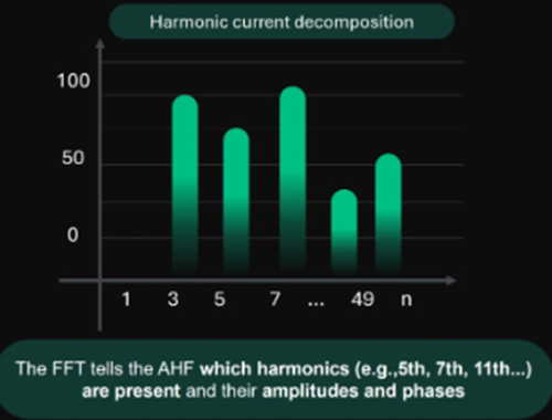
- Real time FFT harmonic detection is appliedto break down the complex current waveform into its frequency components:
This is done using an IGBT PWM inverter AHF- “Equipped with a high-speed IGBT PWM inverter, the Active Harmonic Filter dynamically responds to load variations, delivering consistent THD reduction even under rapidly changing conditions.
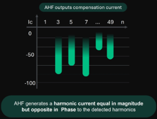
- The compensating harmonic current isinjected into the linethrough a coupling inductor
- This current cancels out the harmonic componentsin the load current.
- The source (utility or generator) now supplies only thefundamental current.
Ideal For
- Plants with high harmonic distortion (THD > 8%)
- VFD-based machinery
- UPS and IT loads
- Data centers
- Welding machines
- Elevators
- Printing & packaging industries
- Commercial buildings with non-linear loads
- Facilities facing transformer overheating
Key Benefits
- Filters harmonics from 2nd to 51st order
- Reduces THDi to <5%
- Real-time response with high-speed DSP control
- No risk of resonance
- Improves system reliability & equipment life
- Corrects reactive power support for both inductive & capacitive loads
- Works with 3P3W and 3P4W networks
- Modular design with parallel expansion option
Technical Advantages
- IGBT-based inverter technology
- Fast switching for accurate compensation
- Neutral current mitigation in 4-wire systems
- Advanced FFT analysis with closed-loop feedback
- RS485 / MODBUS / optional wireless monitoring
- Natural/forced air cooling options
Technical Data Sheet
Electrical Specification | |
Rated Voltage | 400V(300~456V) |
Rated Current | 15/25/50/75/100/150A |
Circuit Topology | Three Level IGBT |
Network Configuration | 3P3W/ 3P4W |
Mains Frequency | 50/60Hz±5% |
Filter range | 2nd~51st odd order harmonics |
Filtering Performance | Typically, THDi≤ 5% at rated load |
Target Power Factor | Adjustable from -1.0 to +1.0 |
3 Phase Load Balancing Effect | ≤5%, Mitigate negative and zero sequence |
Overall Response time | ≤5ms |
Multi devices in parallel | Up to 12 sets can be connected in parallel |
Output current limit | Automatically limited within 100% of rated capacity to output |
Control Technology | |
Switching/control frequency | 25.6kHz |
Control algorithm | Intelligent FFT, Self-adaptive control algorithm |
Communication protocols | communication interface adopts RS485 and CAN bus, supporting mobile phone APP operation |
Physical Specification | |
Human Machine Interface | 7 inch touched LCD HMI |
Installation method | Rack mounted, wall mounted |
Level of protection | IP20 |
Environmental Specification | |
Environment temperature | -20 ~ 55 ℃ (rated power output) |
Storage temperature | -30~70℃ |
Relative humidity | 95 % at a maximum, no condensation |
Altitude | Below 1500 meters above sea level |
Cooling requirements | Require well ventilation, and the air vent can be opened through the cabinet door, or a fan installed in the cabinet |
Products Portfolio


Typical Applications

Industries using VFD-driven motors

Solar inverter-based plants

Plastic, textile, metal & food processing plants

Data centres & IT parks

Commercial buildings with heavy non-linear loads

